Sole E95 Elliptical Assembly
_thm.jpg)
_thm.jpg)
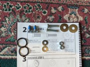
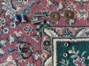
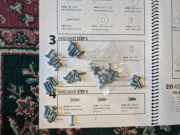
,%20Splits%20(182),%20Flats%20(170)%20%26%20Stars%20(183,%20below)_thm.jpg)
_thm.jpg)
_thm.jpg)
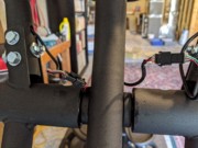
%20conveniently%20for%20wiring,%20top%20on%20floor_thm.jpg)
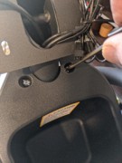
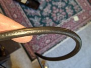
%20is%20too%20bulky%20to%20pull%20through%20the%20mast_thm.jpg)
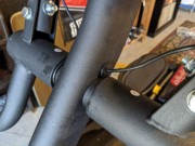
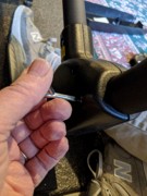
%20twist%20tie%20passes%20axle_thm.jpg)
%20twist%20tie_thm.jpg)
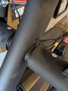
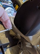
%20twist%20tie%20from%20top%20of%20Mast%20(by%20floor)_thm.jpg)
%20out%20the%20top%20of%20the%20Mast_thm.jpg)
,%20Split%20(180)%20%26%20Flat%20(164)%20assemblies_thm.jpg)
_thm.jpg)
_thm.jpg)
_thm.jpg)
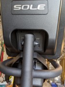
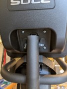
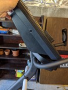
%20on%20Mast%20(12)_thm.jpg)
_thm.jpg)
_thm.jpg)
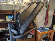
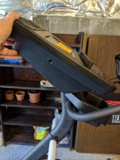
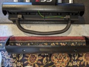
,%20face%20down%20on%20my%20weight%20bench._thm.jpg)
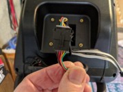
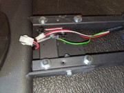
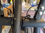
%20console%20cables_thm.jpg)
%20console%20cables_thm.jpg)

_thm.jpg)
%20by%20hand_thm.jpg)
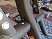
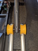
%20onto%20each%20side%20of%20axle_thm.jpg)
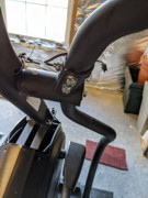
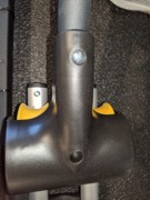
%20lower%20handle%20bar%20arm_thm.jpg)
%20arm%20onto%20right%20side%20of%20axle_thm.jpg)
%20and%20Flat%20(165)%20into%20left%20end%20of%20axle_thm.jpg)
%20and%20Flat%20(165)%20into%20right%20end%20of%20axle_thm.jpg)
%20found%20on%20floor,%20from%20rod%20end%20of%20left%20lower%20handle%20bar%20arm_thm.jpg)
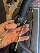
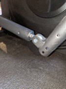
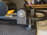
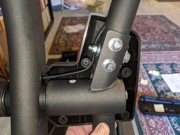
%20%20inserted,%20fit%20rod%20end%20into%20slot%20and%20insert%20Bolt%20(134)_thm.jpg)
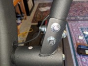
%20and%20Nut%20(159)%20onto%20Bolt_thm.jpg)
%20into%20rod%20end%20of%20right%20lower%20arm_thm.jpg)
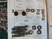
%20assemblies%20with%20Nuts%20(187),%20two%20with%20Curved%20(181)%20and%20four%20with%20Flat%20(164)%20washers_thm.jpg)
%20next%20to%20installed%20left%20Lower%20Arm%20(13)_thm.jpg)
,%20two%20of%20six%20holes%20this%20side_thm.jpg)
_thm.jpg)
_thm.jpg)

_thm.jpg)
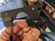
%20to%20each%20arm%20wire_thm.jpg)

%20with%20four%20Sheets%20(142)_thm.jpg)
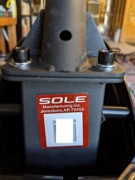
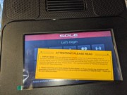
%3B%20be%20sure%20you%20recorded%20serial%20number%20on%20page%201_thm.jpg)
![E95 Step 4-01 04 Insert Sheet Metal Screws (142) from right side and tighten [four screws].jpg](E95%20Step%204-01%2004%20Insert%20Sheet%20Metal%20Screws%20(142)%20from%20right%20side%20and%20tighten%20%5Bfour%20screws%5D_thm.jpg)
%20with%20four%20Sheets%20(142)_thm.jpg)
%20with%20two%20Sheets%20(142)%20and%20two%20Machines%20(139)%20each_thm.jpg)
_thm.jpg)
%20with%20short%20driver%20(185)_thm.jpg)
%20using%20short%20driver_thm.jpg)
%20each%20side,%20and%20two%20Sheets%20(142,%20top%20%26%20bottom)%20on%20outside_thm.jpg)
![E95 Step 4-04 01 Two outer Connecting Arm Covers (109 & 110), with four Sheets (142) and four Machines (139) [error in manual].jpg](E95%20Step%204-04%2001%20Two%20outer%20Connecting%20Arm%20Covers%20(109%20%26%20110),%20with%20four%20Sheets%20(142)%20and%20four%20Machines%20(139)%20%5Berror%20in%20manual%5D_thm.jpg)
_thm.jpg)
%20with%20two%20Machine%20screws%20(139)%20each_thm.jpg)
%20with%20one%20Machine%20screw%20each_thm.jpg)
_thm.jpg)
_thm.jpg)
_thm.jpg)
,%20four%20Stubby%20Machine%20Screws%20(145),%20Incline%20Cover%20(115)%20%26%20two%20Machine%20Screws%20(139)_thm.jpg)
,%20angled%20to%20rear,%20with%20stubby%20machine%20screws%20(145)_thm.jpg)
,%20angled%20to%20rear,%20with%20stubby%20machine%20screws%20(145)_thm.jpg)
_thm.jpg)
%20with%20two%20Machine%20Screws%20(139)_thm.jpg)

,%20Right%20covers%20(bottom,%20etched%20R),%20four%20Sheets%20per%20set_thm.jpg)

_thm.jpg)
_thm.jpg)
%20with%20four%20Machine%20screws%20(139)_thm.jpg)
,%20and%20flip%20the%20switch%20on_thm.jpg)
_thm.jpg)
_thm.jpg)
_thm.jpg)
_thm.jpg)
![E95 Step 4-11 09 All done, but two Machine Screws (139) left over [probably for model E95S].jpg](E95%20Step%204-11%2009%20All%20done,%20but%20two%20Machine%20Screws%20(139)%20left%20over%20%5Bprobably%20for%20model%20E95S%5D_thm.jpg)
_thm.jpg)
_thm.jpg)